Description
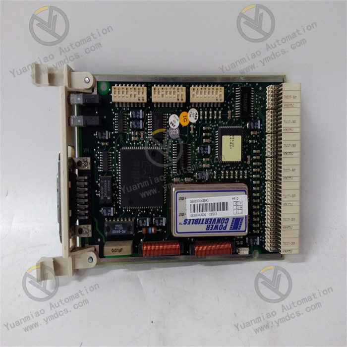
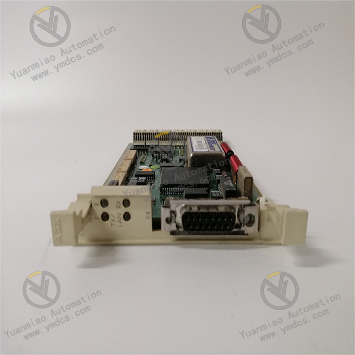
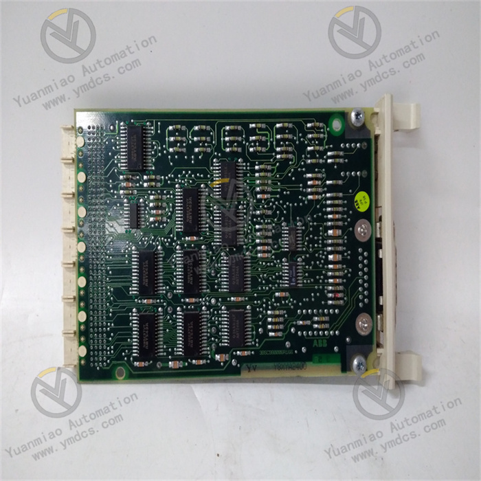
ABB CS513 3BSE000435R1
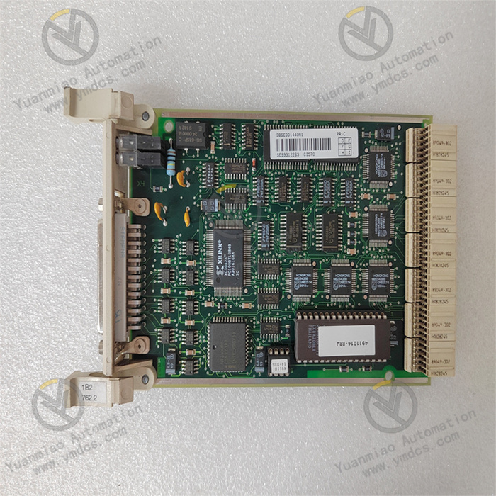
ABB CS513 3BSE000435R1 is a communication interface module, serving as a core component for realizing data interaction between devices in industrial automation control systems. Its core positioning is to build a communication bridge between traditional industrial equipment and control systems, enabling stable data transmission and control command interaction between ABB ACS series drives, basic industrial control units, as well as PLCs, upper computers, HMIs and other devices. Relying on mature bus communication technology and high-reliability design, it is widely used in industrial scenarios with basic requirements for communication stability, such as small and medium-sized industrial production lines, general electromechanical equipment control, auxiliary power systems, and heating, ventilation and air conditioning (HVAC), providing reliable communication support for the automated operation of industrial systems.
I. Product Features
1. Classic Bus Protocol Compatibility, Stable Communication Guarantee
2. Accurate Data Processing, Suitable for Basic Control Scenarios
3. Wide System Compatibility, Flexible Expansion
4. Industrial-grade Reliable Design, Strong Environmental Adaptability
5. Convenient Configuration and Operation & Maintenance, Reducing Usage Costs
II. Technical Parameters
1. Basic Parameters
- Model: ABB CS513 3BSE000435R1
- Product Type: Industrial-grade communication interface module
- Product Series: MasterBus 300 communication interface module series
- Core Functions: Inter-device data transmission, control command interaction, basic fault diagnosis, signal acquisition and processing
- Compatible Systems: ABB ACS510 series drives, Advant Controller 410 control system
- Communication Protocols: Modbus RTU/ASCII, MasterBus 300
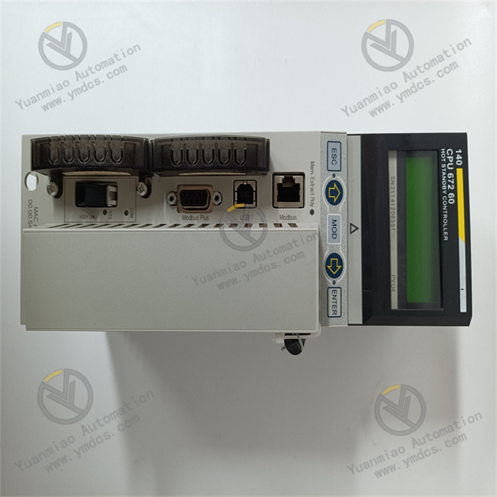
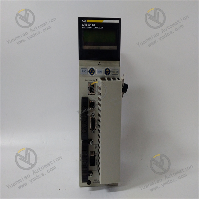
- Interface Types: RS-232, RS-485, USB 2.0, expansion interface
- Configuration Methods: Local menu configuration, dedicated software configuration
- Installation Method: TS35 standard rail mounting
- Maintenance Methods: Online debugging, on-site fault diagnosis, module replacement
2. Electrical Parameters
- Supply Voltage: 24V DC ±20%
- Power Consumption: Typical value 1.8W, maximum 2.5W
- Maximum Input Current: 0.5A
- Analog Input Range: 0~10V DC voltage signal, 4~20mA current signal
- Analog Output Range: 0~10V DC voltage signal, 0~20mA current signal
- Sampling Rate: 50kHz
- Resolution: 12-bit
- Signal Acquisition Error: ≤±0.1% FS
- Communication Rate: RS-485 interface up to 115.2 kbps, RS-232 interface up to 9600 bps
- I/O Points: 32 points (16 digital inputs, 16 digital outputs, expandable to 64 points)
- Input Type: Single-ended input
- Output Type: Relay output
- Output Frequency: 100Hz
- Program Capacity: 500
- Data Capacity: 200
3. Environmental Parameters
- Operating Temperature: -20°C ~ +65°C
- Storage Temperature: -40°C ~ +85°C
- Relative Humidity: 5% ~ 95% RH (no condensation)
- Protection Rating: IP20
- Vibration Resistance: Compliant with IEC 60068-2-6 standard (10~500Hz, acceleration 5g)
- Shock Resistance: Compliant with IEC 60068-2-27 standard (peak acceleration 30g, duration 11ms)
- Electromagnetic Compatibility: Compliant with EN 55011 and EN 55022 industrial electromagnetic interference protection standards
- Certification Standard: CE certification
4. Physical Parameters
- Dimensions: 85mm×30mm×28mm (W×H×D)
- Net Weight: Approximately 0.1kg ~ 0.15kg
- Housing Material: Industrial-grade flame-retardant plastic
- Terminal Type: Plug-in phoenix terminal
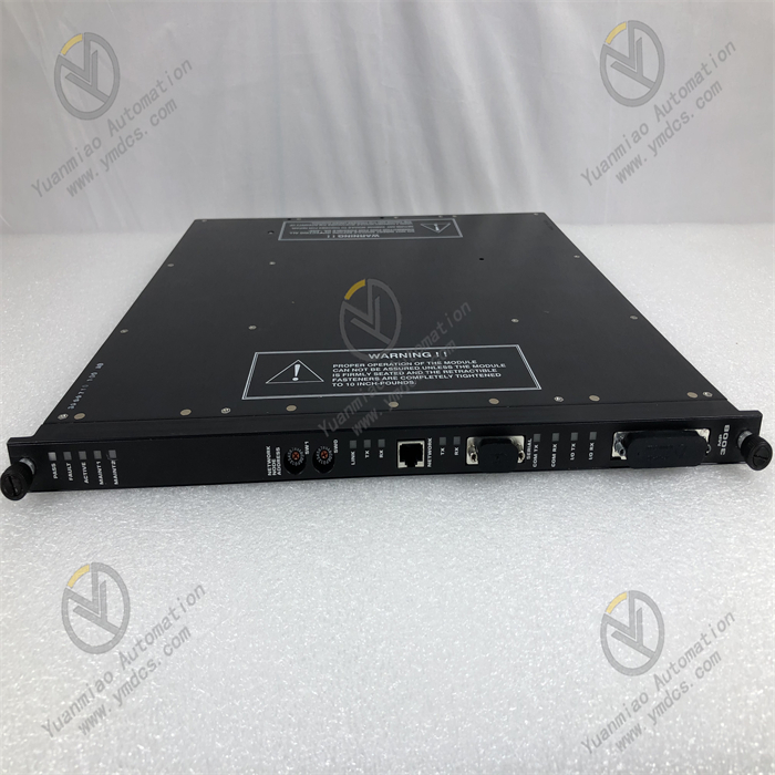
- Status Indicators: Power light (PWR), Run light (RUN), Communication status light (COMM), Fault light (FAULT)
III. Working Principle
The core working logic of the ABB CS513 3BSE000435R1 communication interface module is "Power Supply - Protocol Adaptation - Data Acquisition - Processing and Transmission - Status Monitoring - Fault Alarm". It realizes stable communication between industrial equipment through the collaboration of multiple links, with the specific workflow as follows:
- Power Supply and System Initialization: The module is connected to a standard 24V DC power supply. The internal power module performs voltage stabilization, filtering and reverse polarity protection to provide stable power for core components such as the processor, communication interface and data storage. At the same time, it automatically loads preset configuration parameters and protocol configuration information, completes the self-test of core components and interfaces, enters the ready state after passing the self-test, and waits to establish a communication connection with external devices.
- Protocol Adaptation and Link Establishment: According to the preset configuration parameters, it automatically matches the communication protocol of the target device (Modbus RTU/ASCII or MasterBus 300), and establishes a communication link with PLCs, upper computers, ACS510 drives and other devices through RS-232/RS-485 interfaces. It supports adaptive calibration of communication parameters and can real-time monitor the protocol interaction status to avoid communication abnormalities caused by parameter mismatch.
- Data Acquisition and Processing: It real-time collects the operation parameters of field devices, sensor detection data and device status signals through input interfaces, converts analog signals into digital signals and transmits them to the processor. The internal signal processing circuit performs filtering and noise reduction on the collected data to eliminate interference signals and ensure the accuracy of data acquisition.
- Data Transmission and Command Interaction: The processor encapsulates the processed data according to the adapted communication protocol and transmits it to target devices such as upper computers or PLCs through communication links. Meanwhile, it receives control commands or configuration parameters issued by target devices, parses them and transmits them to corresponding actuators or drives to drive the devices to complete corresponding actions, realizing automatic control of the devices.
- Status Monitoring and Fault Alarm: The system real-time monitors its own power supply status, communication link connection status, data transmission integrity and internal component working status, and identifies abnormal conditions (such as communication interruption, data packet loss, power supply abnormality, parameter error, etc.) through built-in diagnostic logic. When a fault is detected, it immediately turns on the fault indicator light and records the fault code and fault occurrence time in the internal log. At the same time, it sends fault alarm information to the upper system through the communication link, facilitating timely intervention and handling by operation and maintenance personnel.
IV. Common Fault Troubleshooting
| Fault Phenomenon | Possible Causes | Troubleshooting and Solutions |
|---|---|---|
| Power light off, module unresponsive | Abnormal supply voltage; reversed power polarity; poor contact of power supply lines; internal power module failure | Use a multimeter to measure the supply voltage to ensure it is 24V DC±20%; check the positive and negative power connections to avoid polarity reversal; inspect the terminal connections of the power supply lines, re-plug and tighten them, and check for terminal oxidation or line damage; if the power supply and wiring are normal but the module is still unresponsive, judge that the internal power module is faulty and contact after-sales service for repair or replacement. |
| RS-485 communication interrupted, unable to interact with drives | Mismatched communication parameters; damaged/poor contact of communication cables; terminal resistor not configured; signal interference | Check that the communication parameters (address, baud rate, data bits/stop bits) of the module and the drive are consistent; inspect the RS-485 communication cable, replace the damaged cable, re-plug the terminal to ensure firm contact; configure 120Ω terminal resistors at both ends of the RS-485 bus to improve signal stability; keep the communication cable away from strong interference sources such as frequency converters and motors, or replace it with a twisted-pair shielded cable and ensure single-ended grounding of the shield layer. |
| Inaccurate data acquisition with large errors | Sensor failure; interference of input signal cables; abnormal signal processing circuit; incorrect sampling parameter configuration | Test the sensor separately to confirm that the sensor output signal is normal; inspect the input signal cable, keep it away from strong interference sources, replace it with a shielded cable and ensure reliable grounding; check the sampling parameter configuration through configuration software to ensure that the range matches the sensor output range; if the above troubleshooting is normal, judge that the internal signal processing circuit is faulty and contact after-sales service for repair. |
| Unable to connect to the module through configuration software | USB/RS-232 cable failure; mismatched communication parameters; incompatible configuration software version; interface failure | Replace the USB/RS-232 communication cable, re-plug it to ensure firm contact; check that the communication parameters of the module and the configuration software are consistent; upgrade the configuration software to a version compatible with the module; use a multimeter to measure the interface pin voltage; if abnormal, judge that the interface is faulty and contact after-sales service for repair. |
| Module frequently crashes or restarts | Excessive fluctuation of power supply voltage; excessively high ambient temperature/poor heat dissipation; parameter configuration conflict; outdated firmware version | Install a regulated power supply to ensure stable supply voltage; check the module installation environment, avoid close contact with heat-generating equipment to ensure smooth heat dissipation; restore the module default parameters through configuration software and reconfigure to eliminate parameter conflicts; confirm the module firmware version, and upgrade to the latest compatible version if outdated. |