Description
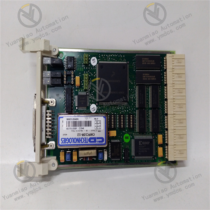
ABB CI546 3BSE012545R1
ABB CI546 3BSE012545R1 is a communication module specially designed and developed for field device interconnection and data interaction in Distributed Control Systems (DCS). As a key communication hub between the controller and various field intelligent devices as well as remote I/O modules, the module achieves high-speed data interaction with the AC 800M main controller via the backplane bus. Meanwhile, it supports multiple industrial communication protocols, enabling flexible connection with lower-level devices such as frequency converters, sensors and actuators to realize real-time data transmission, status monitoring and command issuing. It is widely used in industrial fields with stringent requirements for communication stability and reliability, including power, petrochemical, metallurgical and building materials industries, providing core communication support for the efficient and coordinated operation of large-scale industrial control systems.
It features core advantages such as strong protocol compatibility, high communication rate, redundant backup and fault self-diagnosis. The modular structure design supports hot swap function, and combined with the standard DIN rail mounting method, it greatly improves the convenience of on-site installation and operation & maintenance, effectively reduces the cost of system shutdown maintenance, and ensures the continuity of the production process.
It mainly supports the PROFIBUS DP-V1 communication protocol and is compatible with the DP-V0 specification. It can realize efficient interaction of cyclic data (real-time control signals, equipment operating parameters) and acyclic data (equipment diagnostic information, parameter configuration commands), meeting the diversified communication needs in complex industrial scenarios. With a maximum communication rate of up to 12 Mbps, it supports automatic baud rate detection and adaptation function, which can flexibly adjust the transmission rate according to the field network environment to ensure the efficiency and stability of data transmission.
It supports redundant master station configuration. Two CI546 modules can be connected to the same PROFIBUS network in parallel to build an active-standby hot redundant communication architecture. When the master module encounters communication failures or hardware abnormalities, the standby module can seamlessly take over the bus control right within milliseconds, ensuring uninterrupted communication links and the continuity of the production control process. The module is built-in with a high-performance power conversion unit, featuring multiple electrical protection functions such as overvoltage protection, reverse connection protection and anti-electromagnetic interference, which can adapt to the harsh electromagnetic environment and voltage fluctuations in industrial sites.
It is equipped with a complete built-in status monitoring and fault diagnosis mechanism, which can real-timely monitor key information including bus communication status, slave device connection integrity, data transmission error count and module self-operation status. Diagnostic data can be synchronously uploaded to the main controller and upper monitoring system via the backplane bus. Meanwhile, the front panel of the module is provided with multiple groups of LED status indicators, which intuitively display power status, operation status, bus activity and fault alarm information, facilitating on-site operation and maintenance personnel to quickly locate fault points and improve fault troubleshooting efficiency.
The modular structure design supports flexible system expansion, achieving perfect compatibility with ABB AC 800M series controllers and 800xA DCS systems. Meanwhile, it can seamlessly integrate third-party slave devices complying with the PROFIBUS DP protocol, greatly improving the flexibility of system construction. It supports hot swap function, allowing module replacement, maintenance and upgrade without stopping the system, thus effectively reducing the risk of system shutdown and operation & maintenance costs.
Parameter configuration is supported via ABB CBF (Control Builder F) configuration software. The graphical operation interface simplifies the configuration process of communication parameters, slave station information, redundancy strategies, etc. The module is built-in with a parameter storage unit, where the configured parameters can be permanently saved without loss even in case of power failure. It also supports backup and restoration of configuration parameters, further enhancing the convenience of operation and maintenance.
- Model: CI546
- Ordering Code: 3BSE012545R1
- Brand: ABB
- Product Type: Industrial-grade PROFIBUS DP-V1 Communication Module
- Applicable Systems: ABB AC 800M Controller, 800xA DCS System (supporting V5.1 and subsequent versions)
- Mounting Compatibility: Suitable for AC 800M controller rack and FLD distributed rack
- Communication Protocol: PROFIBUS DP-V1 (compatible with DP-V0)
- Maximum Transmission Rate: 12 Mbps
- Number of Supported Slaves: Up to 126 PROFIBUS DP slave stations
- Communication Interface: 1× PROFIBUS 9-pin Sub-D electrical interface
- Bus Topology: Bus topology supported
- Communication Distance: Up to 100m (12 Mbps) ~ 1200m (9.6 kbps) depending on baud rate
- Terminal Resistor: Support for switching between built-in/external terminal resistors (120Ω)
- Power Supply Mode: Powered via backplane bus (+5VDC)
- Power Consumption: Typical value 1.5 W, maximum value 2 W
- Power Supply Protection: Equipped with overvoltage protection (≥6.5VDC) and reverse connection protection (≤-3VDC) functions
- Redundant Power Supply: Support for CEX bus redundant power supply expansion
- Operating Temperature: 0°C ~ 60°C
- Storage Temperature: -40°C ~ 85°C
- Relative Humidity: 5% ~ 95% (non-condensing)
- Protection Grade: IP20 (compliant with EN 60529 standard)
- Altitude: ≤2000m (derating required if exceeded)
- Pollution Degree: Degree 2 (compliant with IEC 61131-2 standard)
- Electromagnetic Compatibility: Compliant with EN 55011/EN 55022 Class A standard
- Mounting Method: Standard 35mm DIN rail mounting or plug-in rack mounting
- Dimensions: 59mm (width) × 186mm (height) × 127mm (depth)
- Net Weight: Approximately 0.6 kg
- Housing Material: Industrial-grade flame-retardant ABS plastic
- LED Indicators: Power Light (PWR), Run Light (RUN), Bus Activity Light (BUS), Fault Light (FAULT)
The core working logic of the ABB CI546 3BSE012545R1 module is "Controller Interaction - Protocol Conversion - Field Communication - Status Feedback". It realizes efficient data interaction between the controller and field devices through the collaboration of multiple links, and the specific working process is as follows:
Controller Interaction: The module establishes a stable connection with the AC 800M main controller via the backplane bus, receives control commands and communication parameter configuration information issued by the controller, and feeds back the operation data and status information uploaded by field devices to the controller, realizing high-speed two-way data interaction.
Protocol Conversion: The built-in dedicated protocol processing chip converts the internal data format of the controller into the standard format of the PROFIBUS DP-V1 protocol to ensure that the data can be recognized by field slave devices. At the same time, it reversely converts the DP protocol data uploaded by slave devices into a format parsable by the controller, realizing compatible transmission of cross-device data.
Field Communication: It establishes communication links with field slave devices through the PROFIBUS 9-pin Sub-D interface, completes real-time transmission of cyclic data (such as controller's speed control commands for frequency converters and sensor acquisition data) according to the preset baud rate and communication cycle, and processes acyclic data interaction, such as reading equipment diagnostic information and parameter configuration.
- Status Feedback and Redundancy Protection: It real-timely monitors the integrity of communication links, data transmission error rate and the module's self-operation status. When faults such as communication interruption, slave station offline and parameter abnormality are detected, it immediately issues an alarm via LED indicators and uploads fault information to the controller. If redundancy configuration is enabled, the standby module switch is automatically triggered when the master module fails, ensuring continuous and stable communication links and uninterrupted production control.
Parameter configuration is completed via ABB CBF configuration software, and the core configuration items and requirements are as follows:
Communication Parameter Configuration: Set the PROFIBUS bus address (via software configuration or module DIP switch setting) to ensure the address is unique without conflict. Select the communication rate (supporting 9.6 kbps - 12 Mbps). It is recommended to choose according to the communication distance: 12 Mbps for short distance (≤100m), 1.5 Mbps for medium distance (100-500m), and lower baud rate for long distance (>500m). Enable the automatic baud rate detection function (optional) to improve communication flexibility.
- Slave Station Configuration: Add the model, address and communication parameters of field slave devices, set the data exchange cycle and data mapping relationship (such as input/output byte length and address offset), supporting up to 126 slave devices. After configuration, it is necessary to verify the validity of slave addresses to avoid address conflicts.
Redundancy Configuration (Optional): If the redundancy function is enabled, add a standby CI546 module, configure the master-standby module addresses, switching conditions and synchronization parameters to ensure data synchronization between the master and standby modules with a switching delay ≤10ms.
- Alarm Parameter Configuration: Set the alarm thresholds and delay times for faults such as communication interruption, slave station offline and data transmission error, and configure the fault information upload method (real-time upload to the controller or upper system).
- Parameter Saving and Backup: After configuration is completed, click "Download" to write the parameters into the module, and back up the configuration file locally for easy later maintenance and parameter restoration.
After power-on, conduct comprehensive debugging and functional verification with the following steps:
Power-on Check: Observe the LED indicators on the front panel of the module. The Power Light (PWR) should be steadily on in green, the Run Light (RUN) should be steadily on in green, and the Fault Light (FAULT) should not be on. If the indicator status is abnormal, check whether the power connection and module installation are normal.
- Communication Link Verification: Check the connection status between the module and the controller via the CBF configuration software to confirm normal connection. Check the communication status of each slave device to ensure all slaves are online and communicating normally without packet loss or bit errors.
Data Transmission Verification: Issue test control commands (such as frequency converter speed adjustment commands) to check whether field devices can respond accurately. Collect the operating parameters of field devices (such as sensor measurement values) to confirm that the parameters can be uploaded to the controller in real time with data transmission delay meeting the requirements (≤10ms@12 Mbps).
- Redundancy Function Verification (if enabled): Manually disconnect the power supply or communication link of the master module, observe whether the standby module can quickly take over the communication (switching time ≤10ms), with slave devices communicating without interruption and the controller receiving data normally. After restoring the master module, check whether it can automatically synchronize and switch back to the master module operation.
- Fault Alarm Verification: Simulate communication interruption (by disconnecting the wiring of a slave device), check whether the module can accurately identify the fault and issue an alarm, and whether the fault information is correctly uploaded to the controller. After restoring the wiring, confirm that the alarm can be cleared normally.
![]()