Description
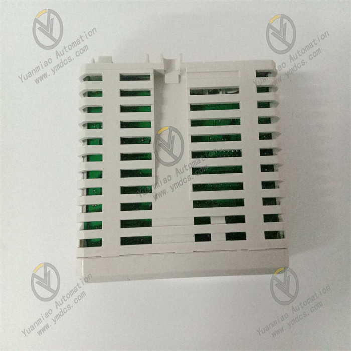
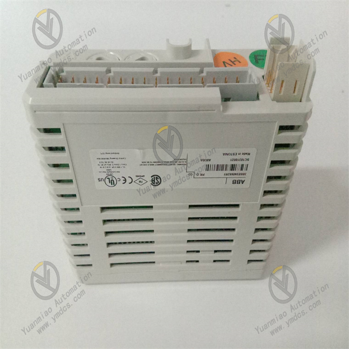
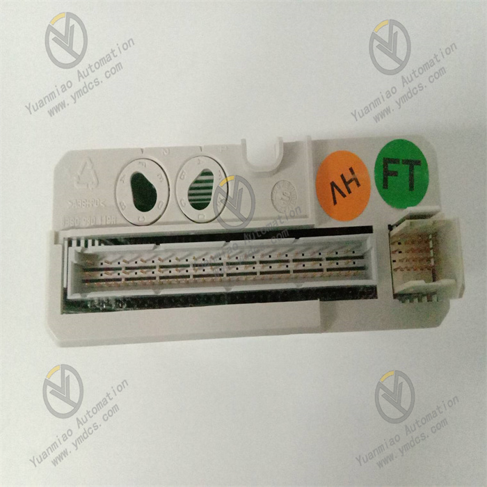
AI830A 3BSE040662R1
I. Product Overview
ABB AI830A 3BSE040662R1 is an 8-channel isolated analog input module, serving as the channel-expanded and performance-optimized version of the AI825 module. Its core function is to synchronously collect analog signals (current/voltage type) output by 8 industrial field sensors (for pressure, temperature, flow, liquid level, etc.). After undergoing independent isolation, precision filtering, and high-resolution analog-to-digital conversion, these signals are stably transmitted to the DCS/PLC main controller, providing high-density and high-reliability data support for large-scale industrial process control.
II. Functional Features
8-Channel Fully Independent Isolation and Flexible Multi-Signal Adaptability
- Equipped with 8 fully independent electrically isolated channels (achieving 250V AC isolation between channels and between channels and ground), it completely eliminates signal crosstalk between channels and external electromagnetic interference. It supports simultaneous data collection from 8 different types of sensors, greatly improving the stability and data accuracy of multi-parameter synchronous monitoring.
- Fully compatible with standard analog signal inputs: current signals (-20~+20mA, 0~20mA, 4~20mA) and voltage signals (-10~+10V, 0~10V, 2~10V, ±5V). Each channel's signal type and range can be independently configured via software without on-site jumpers, flexibly adapting to different types of sensors for temperature, pressure, flow, etc., and reducing the types of modules required for inventory.
Ultra-High Precision Acquisition and Low-Drift Characteristics
- With measurement accuracy improved to ±0.05% (at 25℃) and resolution up to 16 bits plus sign bit, compared with the 14-bit resolution of the AI825, it can accurately capture smaller signal changes (minimum distinguishable signal ≤ 1μV), making it suitable for high-precision measurement scenarios such as precision pressure control and micro-flow monitoring.
- Boasts excellent temperature stability, with current signal temperature drift ≤ 30ppm/℃ and voltage signal temperature drift ≤ 20ppm/℃. The measurement accuracy fluctuation is minimal within the wide temperature range of -25℃~+70℃, avoiding the impact of ambient temperature changes on data acquisition accuracy.
- Supports sensor wire break detection function, which can quickly identify faults such as loose sensor wiring and wire breaks, and feed back the information to the controller in a timely manner, reducing the difficulty of fault troubleshooting.
Industrial-Grade Enhanced Anti-Interference and Safety Protection
- Upgraded Electromagnetic Compatibility (EMC) performance, with Common Mode Rejection Ratio (CMRR) ≥ 130dB (50/60Hz) and Normal Mode Rejection Ratio (NMRR) ≥ 60dB (60Hz). It has passed the highest level anti-interference tests in the IEC 61000-4 series, and can resist strong electromagnetic radiation and power grid fluctuation interference generated by frequency converters and high-voltage equipment in industrial sites, ensuring distortion-free signal transmission.
- Built-in multiple safety protection mechanisms: current channels support 30V DC overvoltage protection, and voltage channels support 8V DC overvoltage protection. Combined with PTC resistor current-limiting and reverse polarity protection design, it effectively resists impacts such as sensor wiring errors and power supply abnormalities, extending the service life of the module.
- Natively supports HART 7.0 protocol pass-through function. Input channels can be directly connected to intelligent sensors with HART protocol without additional isolators or gateways, realizing parallel analog signal acquisition and digital communication, simplifying the system architecture and supporting remote sensor configuration and diagnosis.
High Reliability and High-Density Installation Adaptability
- Adopts industrial-grade high-stability components and sealed protection design (IP20). It operates within a temperature range of -25℃~+70℃ and a humidity range of 5%-95% (non-condensing). Its vibration and shock resistance performance complies with IEC 60068 standards, enabling long-term stable operation in harsh industrial environments with high temperature, high humidity, and heavy dust, with a Mean Time Between Failures (MTBF) ≥ 400,000 hours.
- The module is powered by the bus (24V DC), with a typical power consumption of only 3.5W and a maximum power consumption ≤ 4.2W. Even in the 8-channel high-density configuration, it maintains low heat dissipation characteristics, suitable for high-density cabinet installation scenarios, and greatly saves cabinet space.
Seamless Integration and Convenient Maintenance
- Fully compatible with ABB 800xA, Symphony Plus control systems and S800 I/O series backplane bus. It supports matching use with terminal units such as TU811, TU813, and TU831. After installation, it is automatically recognized by the system without complex protocol configuration, achieving plug-and-play functionality.
- Adopts a compact design (45mm in width, 102mm in depth, 119mm in height) with a weight of only 0.28kg. It has the same dimensions as the AI825 module, allowing direct replacement or parallel installation, and is suitable for standard 35mm industrial guide rails, eliminating the need to modify the cabinet layout during maintenance. Channel configuration and fault diagnosis are all completed through system software, supporting remote parameter modification and fault troubleshooting.
III. Technical Parameters
| Category | Specific Parameters |
|---|---|
| Product Type | S800 I/O Series Enhanced 8-Channel Isolated Analog Input Module |
| Core Functions | 8-channel analog signal acquisition, independent isolation conversion, precision filtering, HART protocol pass-through, fault self-monitoring |
| Channel Configuration | 8 channels, independent electrical isolation between channels and between channels and ground (isolation voltage 250V AC) |
| Input Signals | Current: -20~+20mA, 0~20mA, 4~20mA; Voltage: -10~+10V, 0~10V, 2~10V, ±5V |
| Measurement Accuracy | ±0.05% (25℃, full scale) |
| Resolution | 16 bits + sign bit |
| Input Impedance | Voltage input: 10MΩ; Current input: 50Ω (standard), 50Ω+125Ω (overvoltage protection) |
| Anti-Interference Performance | CMRR: ≥130dB (50/60Hz); NMRR: ≥60dB (60Hz); EMC complies with IEC 61000-4 standards |
| Protocol Support | HART 7.0 protocol (pass-through mode) |
| Protection Features | Overvoltage protection: 30V DC for current channels, 8V DC for voltage channels; Reverse polarity protection; PTC resistor current limiting |
| Transmission Performance | 8-channel synchronous update cycle < 15ms; Input filtering time: configurable (10ms~500ms) |
| Power Supply Parameters | Supply voltage: 24V DC (module bus); Current consumption: typical 120mA (max 140mA) at 24V, typical 90mA (max 120mA) at 5V |
| Physical Parameters | Dimensions: 45mm (W) × 102mm (D) × 119mm (H); Weight: approx. 0.28kg |
| Environmental Adaptability | Operating temperature: -25℃~+70℃; Storage temperature: -40℃~+85℃; Humidity: 5%-95% (non-condensing); Protection class: IP20 |
| Compatible Systems | ABB 800xA, Symphony Plus, S800 I/O series; Compatible with terminal units TU811/TU813/TU831 |
| Application Scenarios | Large-scale petrochemical plants, thermal/nuclear power generating units, intelligent manufacturing production lines, municipal water treatment plants, precision multi-parameter monitoring systems |
IV. Working Principle
The core working logic of ABB AI830A 3BSE040662R1 is "multi-channel signal acquisition → independent isolation and filtering → high-resolution analog-to-digital conversion → data synchronous transmission → HART communication pass-through → status monitoring and diagnosis", with the specific process as follows:
Multi-channel Signal Acquisition: Analog signals (current/voltage) output by 8 different sensors in industrial sites are respectively connected to corresponding channels through terminal units (e.g., TU813). The module supports field cable connections up to 800 meters long (shielded twisted-pair cable), suitable for long-distance and large-scale monitoring scenarios.
Independent Isolation and Filtering: Each input signal is isolated by an independent isolation circuit to avoid channel crosstalk and external interference. Then, high-frequency noise is filtered out by a programmable low-pass filter circuit. The filtering time can be configured within the range of 10ms~500ms according to signal stability requirements, ensuring signal purity.
High-Resolution Analog-to-Digital Conversion: The filtered analog signal is sent to a 16-bit high-precision ADC converter and converted into a digital signal with a conversion accuracy of ±0.05%, which can accurately capture tiny signal changes (such as μA-level current fluctuations and μV-level voltage changes).
Data Synchronous Transmission: After the 8-channel digital signals are synchronously integrated through the module's internal bus, they are transmitted to the main controller via the S800 I/O backplane bus. The 8-channel synchronous update cycle is < 15ms, meeting the delay requirements of industrial real-time control for multi-parameter synchronous monitoring.
HART Communication Pass-Through: Supports HART 7.0 protocol pass-through function. The digital communication signals and analog signals of HART intelligent sensors are transmitted in parallel, passing through the module to the main controller or HART gateway, realizing remote sensor configuration, parameter modification, and health status diagnosis.
- Status Monitoring and Diagnosis: The module real-time monitors its own power supply status, the signal integrity of each channel (such as overrange and wire break), and the status of the HART communication link. When an abnormality is detected, it automatically uploads the fault code and fault channel information to the controller, facilitating quick problem location.
V. Operation Guide
1. Installation Steps
Installation Environment
Mechanical Installation
- Ensure the main power supply of the control cabinet is cut off. Align the module with the 35mm standard industrial guide rail, push it in and lock it with the buckle to ensure the module is firmly attached to the rail without loosening.
- If matching with a terminal unit (e.g., TU813), install the terminal unit first, then accurately dock and lock the module with the terminal unit.
- When installing multiple modules in high density, maintain a spacing of ≥15mm between modules to avoid heat accumulation affecting operational stability. When mixed with AI825 modules, they can share the same guide rail and terminal unit without additional adaptation.
Wiring Specifications
- Signal Wiring: Connect sensor signal wires according to the terminal markings of the terminal unit. Use two-wire/four-wire wiring for current signals and differential wiring for voltage signals. Select shielded twisted-pair cables (recommended specification: 2×2×0.75mm²), with the shield layer grounded at one end (ground resistance ≤4Ω), and the cable length should not exceed 800 meters.
- HART Sensor Wiring: The wiring method for sensors with HART protocol is the same as that for ordinary analog sensors, without additional wiring. Ensure reliable grounding of the cable shield layer to realize HART signal transmission.
- Notes: Before wiring, confirm that the sensor signal type is consistent with the channel configuration to avoid reverse polarity connection. In overvoltage environments, check the integrity of the cable insulation layer to prevent short circuits from damaging the module.
2. Configuration and Commissioning
Parameter Configuration
- Connect to ABB programming software (e.g., Control Builder Plus, 800xA Engineering). Add the AI830A module in the system configuration interface, independently configure the signal type (current/voltage), input range (e.g., 4~20mA, ±5V), filtering time (10ms~500ms), and fault response strategy (e.g., wire break alarm, overrange alarm) for each channel. Save the configuration and download it to the main controller.
- HART Protocol Configuration: If connecting to HART intelligent sensors, enable the HART pass-through function of the corresponding channel in the software, configure the HART communication rate (default 1200bps), and then establish digital communication with the sensors through the main controller or HART gateway to realize remote parameter reading and configuration.
Power-On Commissioning
- Before the first power-on, verify the correctness of wiring, the consistency between the module model and configuration parameters, and confirm there are no issues such as short circuits or reverse connections. Use a standard signal source to input calibration signals (e.g., 4mA, 20mA current signals, 0V, 10V voltage signals) to each channel to ensure the signal range is consistent with the configuration.
- After powering on, observe whether the module is correctly recognized by the system without fault alarm prompts. If a communication fault occurs, check the reliability of the connection between the module and the backplane bus, and restart the controller to re-recognize the module.
- Accuracy Test: Input standard signals of different ranges to each channel through a standard signal source, read the measured values through the upper software, and verify that the measurement accuracy is within the range of ±0.05%. Test the data consistency during 8-channel synchronous acquisition to ensure there is no obvious deviation.
- HART Function Test: Connect a HART communicator or through upper software to read the device information, measurement parameters, and health status of the HART sensor, send parameter modification commands (e.g., range adjustment), and verify the parallel stability of HART communication and analog signal acquisition.
3. Operation and Maintenance
Status Monitoring
- Normal Status: No fault alarms on the module, 8-channel measured data is stable within a reasonable range, the HART communication link is smooth, and there are no wire break or overrange prompts.
- Fault Status: The system displays fault codes (e.g., channel overvoltage, sensor wire break, HART communication failure). Troubleshoot the problem by combining the fault codes and wiring status.
Regular Maintenance
- Monthly: Clean dust on the module surface and interfaces with dry compressed air, check the firmness of module installation and whether the wiring terminals are loose or oxidized. View the trend of measured data through software to ensure there is no abnormal drift. Check the communication status of HART sensors to ensure no communication interruption.
- Every 6 Months: Conduct a comprehensive inspection of the signal cable insulation layer for damage or aging, and check the reliability of shield layer grounding. Calibrate the measurement accuracy of each channel with a standard signal source to ensure the error ≤ ±0.05%. Back up the module configuration parameters and HART sensor configuration information.
- Annually: Inspect the internal components of the module for signs of aging (such as bulging capacitors, loose interfaces). Test the stability of the HART protocol pass-through function. If the module experiences reduced measurement accuracy or frequent alarms, replace it with original spare parts in a timely manner.
Notes
- Wiring, parameter configuration, and module insertion/removal must be performed with the power off. Live operation is prohibited to avoid short circuits or module damage. When replacing HART sensors, power off first to prevent communication failures caused by hot swapping.
- Do not use the module beyond the channel input range. For example, avoid connecting voltage signals exceeding 30V to current channels, and avoid exceeding the ±10V range for voltage channels to prevent triggering overvoltage protection or burning the internal circuit.
- For modules that have been idle for a long time (more than 6 months), conduct an insulation test (using a 500V megohmmeter, with insulation resistance ≥10MΩ) and functional verification before use, and connect them to the system only after confirming there are no abnormalities. Before enabling the HART function, confirm the protocol compatibility between the sensor and the module (supports HART 7.0 and lower versions).
4. Common Fault Troubleshooting
| Fault Phenomenon | Possible Causes | Troubleshooting Methods |
|---|---|---|
| Large deviation in measured data | Incorrect signal wiring, mismatched channel configuration, deviation of standard signal source | Verify wiring method and polarity; confirm that the channel signal type/range configuration is consistent with the sensor; calibrate the standard signal source |
| Severe data fluctuation | Electromagnetic interference, ungrounded shield layer, excessively long cables, too short filtering time | Strengthen shield layer grounding; shorten cable length (≤800 meters); replace with high-quality shielded twisted-pair cables; increase filtering time (e.g., adjust to 50ms) |
| No data output from the module | Unrecognized module, loose bus connection, abnormal power supply | Check the connection between the module and the backplane bus; restart the controller to re-recognize the module; measure the module supply voltage (24V DC) to see if it is within the ±10% fluctuation range |
| HART communication failure | HART function not enabled, incompatible sensor protocol, poor cable contact | Enable the HART function of the corresponding channel in the software; confirm that the sensor supports HART 7.0 and lower versions; re-tighten the sensor cables |
| Sensor wire break alarm (no actual wire break) | Poor cable contact, abnormal sensor power supply, incorrect channel configuration | Check the reliability of cable connection; measure the sensor supply voltage to see if it is normal; confirm that the channel signal type configuration is consistent with the sensor |
| Module error report (overvoltage protection) | Abnormal sensor power supply, wiring errors, external voltage impact | Measure the sensor supply voltage to see if it exceeds the standard; check whether the signal wire is mistakenly connected to the power supply; troubleshoot cable insulation layer damage and short circuits |