Description
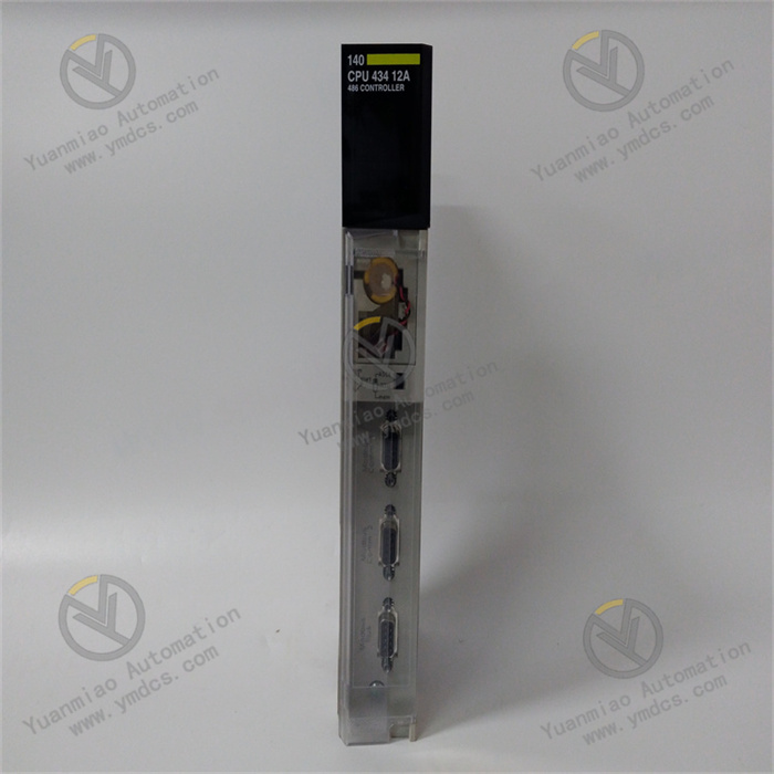
GE IC693CPU351-HT
I. Product Overview
II. Functional Features
High-temperature Adaptability and Industrial-grade Reliability
With enhanced Electromagnetic Compatibility (EMC) design, anti-condensation and anti-corrosion treatment, it has passed IEC 61000-4 anti-interference tests (surge ±2kV, electrostatic discharge ±8kV). It can resist high-frequency electromagnetic interference and harsh environmental erosion in industrial sites, with a Mean Time Between Failures (MTBF) of ≥200,000 hours.
High-performance Computing and Multi-task Processing
Integrated with 512KB program memory and 1MB data memory, it supports a maximum of 16MB extended memory (via memory card), capable of storing massive control programs and process data. Meanwhile, it supports multi-task scheduling (up to 8 priority tasks), enabling parallel processing of logic operation, data acquisition, and communication interaction.
Full Protocol Compatibility and Flexible Communication
It supports seamless connection with all types of RX3i series I/O modules (digital, analog, and special function modules), with a maximum expandable capacity of 256 I/O points. Adapting to distributed control architecture, it meets the equipment access needs of complex industrial scenarios.
Redundant Configuration and Safety Assurance
It has built-in functions such as program password protection, data retention after power failure (powered by supercapacitor or backup battery, with a retention time of ≥72 hours), and fault self-diagnosis. It can monitor CPU operating status, memory integrity, and communication link status in real time. Fault information is fed back through indicator lights and software, facilitating quick troubleshooting.
Convenient Programming and Maintenance
III. Technical Parameters
| Category | Specific Parameters |
|---|---|
| Product Type | RX3i Series High-temperature Environment Specialized CPU Module |
| Core Functions | Control logic operation, multi-task scheduling, I/O data processing, communication interaction, redundancy control |
| Processor | 32-bit RISC processor with a computing speed of 100 MIPS |
| Memory Configuration | Program memory: 512KB; Data memory: 1MB; Supports up to 16MB extended memory (memory card) |
| Programming Languages | Compliant with IEC 61131-3 standard (LD/FBD/ST/SFC/IL) |
| Communication Interfaces | Ethernet: 2×10/100Mbps adaptive ports (full-duplex/half-duplex); Serial: 1×RS-232 port |
| Supported Protocols | Ethernet: EtherNet/IP, Modbus TCP, SNP, EGD; Serial: Modbus RTU |
| I/O Expansion Capability | Supports up to 256 I/O points; Compatible with all RX3i series I/O modules (digital, analog, special function modules) |
| Redundancy Function | Supports Hot Standby redundancy with a switching time of ≤10ms |
| Power Supply Parameters | Operating power supply: 5VDC±5% (provided by RX3i PCI backplane); Power consumption: ≤12W (full load) |
| Environmental Adaptability | Operating temperature: -40°C~+85°C; Storage temperature: -55°C~+100°C; Humidity: 5%-95% (non-condensing); Vibration: 10g (10-2000Hz) |
| Installation Method | RX3i series standard PCI backplane installation (single-slot design) |
| Dimensions | 216mm (L) × 127mm (W) × 40mm (H) (excluding connectors) |
| Weight | Approximately 0.9kg |
| Diagnostic Functions | CPU operating status monitoring, memory integrity detection, communication link diagnosis, redundancy status monitoring, fault code storage |
| Status Indicators | PWR (Power, Green), RUN (Operation, Green), FAULT (Fault, Red), STDBY (Redundant Standby, Yellow) |
| Data Retention | Powered by supercapacitor/backup battery with a data retention time of ≥72 hours |
IV. Working Principle
- Program Loading and Execution: Control programs written via Proficy Machine Edition software (such as PID regulation logic and equipment interlock logic) are downloaded to the CPU module's memory. The CPU executes program instructions one by one according to the preset control cycle (configurable, minimum ≤1ms) to complete logic operations and control decision-making.
I/O Data Interaction: It communicates with extended I/O modules via the PCI backplane bus, collecting digital/analog signals from on-site sensors (temperature, pressure, position) in real time, and converting operation results into control commands sent to actuators (valves, motors, cylinders) to achieve closed-loop control.
Multi-task and Communication Scheduling: It supports parallel scheduling of 8 priority tasks, allocating CPU resources according to priority to ensure that tasks with high real-time requirements (such as emergency shutdown logic) are executed first. It realizes data synchronization with upper-level systems (SCADA/HMI) and remote devices through dual Ethernet ports, and supports EGD global data exchange to achieve multi-controller coordination.
- Redundancy and Fault Handling: In redundant configuration, the active and standby CPUs synchronize programs, data, and I/O status in real time, and the standby CPU continuously monitors the working status of the active CPU. When a fault occurs in the active CPU, the standby CPU automatically switches to the master mode within ≤10ms to ensure control continuity. Meanwhile, the module monitors its own operating status in real time, triggers an alarm and records fault codes upon detecting a fault, facilitating operation and maintenance troubleshooting.
V. Operation Guide
1. Installation Steps
Mechanical Installation:
- Confirm that the power supply of the control cabinet is cut off. Insert the module into the corresponding slot of the RX3i PCI backplane (single-slot design), ensuring that the module is fully attached to the backplane contacts, locked with fixing clips, and installed firmly without loosening.
- For redundant configuration, insert the active and standby CPU modules into adjacent slots respectively, ensuring that the backplane power supply and communication links are independent to avoid mutual interference.
Wiring Specifications:
- Power Wiring: The module obtains 5VDC power supply through the PCI backplane without additional wiring. Before installation, confirm that the backplane power supply is normal (5VDC±5%).
- Communication Wiring: Connect the Ethernet port to an industrial Ethernet switch via an RJ45 interface using shielded Cat5e/Cat6 cables. For redundant communication, connect to dual switches. Connect the RS-232 port to serial devices via a DB9 interface, with a cable length of ≤15m, and the shield layer grounded at one end (grounding resistance ≤4Ω).
- Grounding Treatment: Reliably connect the module's grounding terminal to the protective ground of the control cabinet with a grounding resistance ≤4Ω to enhance anti-interference capability and equipment safety.
2. Configuration and Debugging
- Redundant Configuration: To enable Hot Standby redundancy, install a redundant synchronization cable on the backplane to connect the synchronization interfaces of the active and standby CPU modules. Ensure that the active and standby modules are of the same model and have the same firmware version to avoid compatibility issues.
- I/O Module Adaptation: Connect RX3i series I/O modules according to control requirements, ensuring that the address allocation of I/O modules and CPU modules does not conflict. The backplane automatically identifies the I/O module model.
Software Configuration (GE Proficy Machine Edition):
- Project Creation: Install Proficy Machine Edition software, create a new RX3i project, select the IC693CPU351-HT module model, and configure basic CPU parameters (control cycle, memory allocation, task priority).
- Program Writing: Write control programs using IEC 61131-3 standard languages, supporting modular programming (e.g., dividing PID regulation and interlock logic into independent function blocks) to improve program readability and maintainability.
- Communication Configuration: Set network parameters such as Ethernet port IP address and subnet mask, configure communication protocols (e.g., Modbus TCP master/slave, EtherNet/IP). When enabling EGD data exchange, set the producer/consumer relationship and data update cycle.
- Redundancy Configuration: Enable the Hot Standby redundancy function in the software, set active/standby switching conditions (e.g., active CPU fault, communication interruption), configure data synchronization parameters, and download the configuration and program to the active and standby CPU modules.
Commissioning and Testing:
- Standalone Test: Disconnect the I/O load, start the CPU module, observe whether the RUN light is always on (normal operation), monitor the program execution status through software, and verify the correctness of logic operations.
- I/O Linkage Test: Connect on-site sensors and actuators, trigger control logic (e.g., start the cooling valve when the temperature exceeds the threshold), and verify the accuracy of I/O data collection and control command issuance.
- Redundancy Test: Simulate an active CPU fault (e.g., disconnect the active CPU power supply), observe whether the standby CPU switches to the master mode within ≤10ms, and whether the system control is continuous without data loss.
3. Operation and Maintenance
- Normal Status: PWR is always on, RUN is always on (standalone mode), or the active CPU's RUN is always on / the standby CPU's STDBY is always on (redundant mode), and FAULT is off.
- Fault Status: FAULT is always on or flashing. Read fault codes through software (e.g., "F01 - Memory Error", "F02 - Communication Fault", "F03 - Redundancy Synchronization Abnormality") to locate the cause of the fault.
Regular Maintenance:
- Monthly: Clean dust on the module surface and connector contacts with dry compressed air, check whether the module is installed firmly, and whether the backplane power supply voltage is stable (5VDC±5%). View fault records and redundancy status through software.
- Every 6 Months: Back up control programs and configuration files; test the reliability of the redundancy switching function; check whether the extended memory card (if any) is normal and whether the data retention function is effective.
- Annually: Update the module firmware to the latest version; comprehensively test CPU computing performance and I/O response speed; check the aging status of components (such as capacitors and connectors) in high-temperature environments, and replace them if necessary.
Notes:
- Programming, configuration modification, and module insertion/removal must be performed with the power off. Do not perform live operations to avoid short circuits or module damage.
- For redundant configuration, the programs and configurations of the active and standby modules must be completely consistent, and the firmware versions must be updated synchronously; otherwise, redundancy switching will fail.
- For modules idle for a long time (more than 6 months), conduct high-temperature environment adaptability tests and function verification before commissioning to ensure no abnormalities before connecting to the system.
4. Common Fault Troubleshooting
| Fault Phenomenon | Possible Causes | Troubleshooting Methods |
|---|---|---|
| RUN light off (failure to operate) | Abnormal backplane power supply, improper module installation, CPU fault | Test the 5VDC power supply of the backplane; reinsert the module to ensure good contact; test with a spare CPU |
| FAULT light always on (fault alarm) | Program error, memory damage, I/O address conflict | Read fault codes through software; check for syntax errors in the program logic; reallocate I/O addresses |
| Redundancy switching failure | Redundant synchronization cable not connected, inconsistent active/standby configurations, different firmware versions | Check the synchronization cable connection; ensure that the programs/configurations of the active and standby modules are consistent; upgrade the firmware to the same version |
| Communication failure (unable to connect to HMI) | IP address conflict, incorrect protocol configuration, network cable fault | Reconfigure the CPU IP address; verify that the communication protocol parameters are correct; replace the network cable and switch port for testing |
| Data retention failure | Supercapacitor aging, exhausted backup battery | Replace the backup battery (if any); test supercapacitor performance, replace the module if necessary |
| Frequent faults in high-temperature environments | Ambient temperature exceeding the upper limit, poor heat dissipation, module aging | Check whether the on-site ambient temperature is ≤85°C; optimize control cabinet ventilation; replace the aging module |