Description
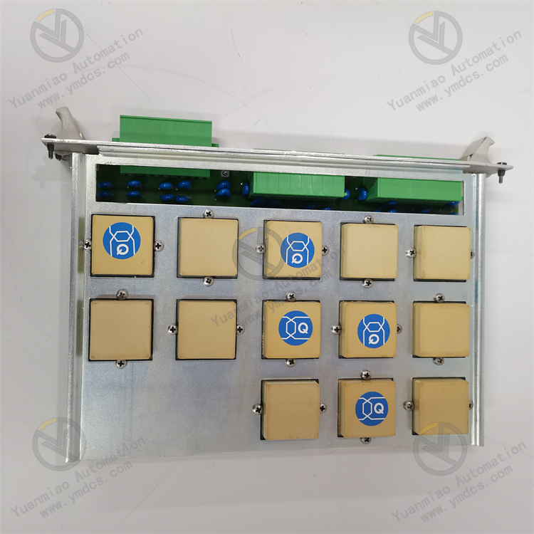
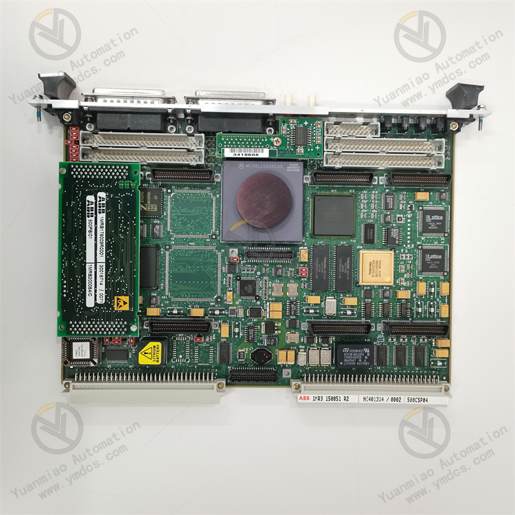
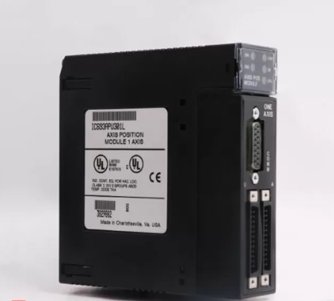
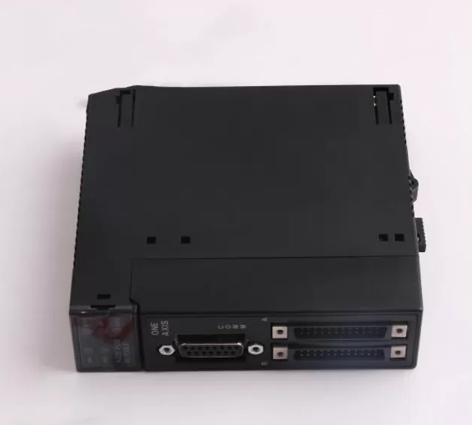
GE IC693APU301
I. Product Overview
II. Functional Features
Wide Voltage Input and Stable Output
Adopting switching power supply topology and high-efficiency filter circuit, it features an output ripple voltage of ≤50mVp-p and a voltage regulation rate of ≤±1%. It can effectively suppress grid fluctuations and harmonic interference, providing pure and stable power supply for precision control modules and ensuring the accuracy of control logic and data processing.
Industrial-grade Reliability and Anti-interference Design
Using industrial-grade components and sealed protection design, it has an operating temperature range of -40℃~+70℃, a storage temperature range of -55℃~+100℃ and a humidity tolerance of 5%-95% (non-condensing). With a Mean Time Between Failures (MTBF) of ≥250,000 hours, it can operate stably for a long time in harsh environments such as high temperature and high humidity.
Multiple Protection and Fault Tolerance
It supports redundant power supply configuration. Two IC693APU301 modules can be connected in parallel to form a redundant power supply system, achieving load sharing. When one of the modules fails, the other module will automatically take over the full load, ensuring power supply continuity and meeting the high reliability requirements of critical industrial scenarios.
High Efficiency, Energy Saving and Low-power Operation
It features low power consumption under no-load conditions, with a no-load power consumption of ≤5W, effectively saving standby energy consumption and meeting the requirements of industrial energy-saving standards and green production.
Convenient Installation and Status Monitoring
III. Technical Parameters
| Category | Specific Parameters |
|---|---|
| Product Type | RX3i Series Standard Industrial Power Supply Module |
| Core Functions | Voltage conversion, stable power supply, multiple protection, redundancy support |
| Input Parameters | AC input: 85~264VAC (50/60Hz); DC input: 120~370VDC; Input current: ≤5A (230VAC) |
| Output Parameters | Output voltage: 5VDC±5%; Output current: 10A (continuous); Output ripple: ≤50mVp-p; Voltage regulation rate: ≤±1% |
| Conversion Efficiency | ≥85% (full load) |
| Protection Functions | Overvoltage Protection (OVP), Overcurrent Protection (OCP), Short-circuit Protection (SCP), Overtemperature Protection (OTP) |
| Redundancy Function | Supports parallel redundant power supply (2 modules in parallel) |
| Environmental Adaptability | Operating temperature: -40℃~+70℃; Storage temperature: -55℃~+100℃; Humidity: 5%-95% (non-condensing); Vibration: 10g (10-2000Hz) |
| Installation Method | RX3i series standard PCI backplane installation (single-slot design) |
| Dimensions | 216mm (L) × 127mm (W) × 40mm (H) (excluding connectors) |
| Weight | Approximately 1.1kg |
| Status Indicators | PWR (Power Normal, Green), FAULT (Fault Alarm, Red) |
| Power Consumption Characteristics | Full-load power consumption: ≤60W; No-load power consumption: ≤5W |
IV. Working Principle
- Voltage Conversion: External AC (or DC) input power is connected through the module terminals. The AC voltage is converted into DC bus voltage by the rectifier circuit, and then the DC bus voltage is converted into high-frequency AC signal by the high-frequency switching circuit (PWM modulation) to realize preliminary voltage level adjustment.
Filtering and Voltage Stabilization: After being isolated and stepped down by the high-frequency transformer, the high-frequency AC signal is rectified into DC voltage again. The ripple and noise are filtered out by the LC filter circuit. Meanwhile, the feedback control circuit monitors the output voltage in real time and dynamically adjusts the PWM modulation duty cycle to ensure that the output voltage is stabilized within the range of 5VDC±5%.
- Load Power Supply: The stable 5VDC output supplies power to load components such as CPU modules and I/O modules through the RX3i PCI backplane bus, meeting the working power supply requirements of each module. In parallel redundant configuration, the two modules achieve load current sharing through the current-sharing circuit, improving power supply reliability.
- Fault Protection: The built-in protection circuit of the module monitors the input voltage, output current and module temperature in real time. When abnormalities such as overvoltage, overcurrent, short circuit or overtemperature are detected, the protection mechanism (output cutoff or current limiting) is triggered immediately, and the FAULT indicator is turned on at the same time to avoid damage to the module and load. The power supply will be automatically restored (or manually reset) after the fault is eliminated.
V. Operation Guide
1. Installation Steps
Mechanical Installation:
- Confirm that the power supply of the control cabinet is cut off. Insert the module into the power slot of the RX3i PCI backplane (usually the leftmost slot or the designated slot of the backplane), ensure that the module is fully attached to the backplane contacts, lock it with the fixing clip, and install it firmly without loosening.
- For redundant configuration, insert two IC693APU301 modules into adjacent power slots, ensure that the backplane power supply bus supports redundant parallel connection, and avoid power supply conflicts caused by wrong slot insertion.
Wiring Specifications:
- Input Wiring: For AC input, connect the L and N phase lines to the "AC IN" terminals of the module, and connect the PE ground wire to the ground terminal. For DC input, connect the positive and negative poles to the "DC IN" terminals (note polarity matching). Use 2.5mm² copper core cables for input wiring, with the shield layer grounded at one end (grounding resistance ≤4Ω).
- Output Wiring: The module automatically supplies power to the load through the PCI backplane without additional output wiring. Before installation, check whether the backplane power supply bus is intact without short circuit or oxidation.
- Grounding Treatment: Reliably connect the module's grounding terminal to the protective ground of the control cabinet with a grounding resistance ≤4Ω to enhance anti-interference capability and equipment safety.
2. Configuration and Debugging
- Single-module Configuration: Insert directly into the power slot, confirm that the input voltage matches the module input range (85~264VAC or 120~370VDC), no additional hardware configuration is required.
- Redundant Configuration: Insert two IC693APU301 modules of the same model and firmware version into adjacent power slots, ensure that the backplane supports redundant power supply. No additional synchronization cables are required between modules, and current sharing and redundant switching are automatically realized through the backplane bus.
Power-on Debugging:
- Before the first power-on, recheck the input voltage polarity and wiring to ensure there is no short circuit or reverse connection.
- Turn on the input power and observe whether the PWR indicator of the module is always on (green). If the PWR indicator is off or the FAULT indicator is always on, cut off the power immediately and troubleshoot the wiring or input voltage issues.
- Load Test: Connect loads such as CPU modules and I/O modules, monitor the output voltage stability (measure the backplane power supply terminal with a multimeter, the voltage should be within the range of 4.75~5.25VDC), and observe whether the module heats abnormally (normal operating temperature ≤60℃).
- Redundancy Test (for redundant configuration): After normal load operation, disconnect the input power of one module, observe whether the other module automatically takes over the full load, and whether the load modules work normally without power supply interruption.
3. Operation and Maintenance
- Normal Status: PWR indicator is always on (green), FAULT indicator is off, and the module has no abnormal heating or noise.
- Fault Status: FAULT indicator is always on (red), which may be caused by abnormal input voltage, output short circuit, overload or internal module fault, requiring immediate troubleshooting.
Regular Maintenance:
- Monthly: Clean dust on the module surface and connector contacts with dry compressed air, check whether the module is installed firmly, and whether the input terminals are loose or oxidized. Measure the input voltage and output voltage to ensure they meet the parameter requirements.
- Every 6 Months: Check whether the module cooling fan (if any) operates normally without jamming or noise. Check whether the insulation layer of the input cable is damaged and whether the grounding is reliable. For redundant configuration, test the reliability of the redundant switching function.
- Annually: Fully test the module's performance parameters such as output ripple and conversion efficiency. Check whether the internal capacitors and heat sinks of the module are aging (e.g., capacitor bulging, heat sink loosening), replace the module if necessary.
Notes:
- Wiring and module insertion/removal must be performed with the power off. Live operation is prohibited to avoid short circuit or electric shock risks.
- It is forbidden to use the module beyond the input voltage range and output current limit, otherwise the protection mechanism will be triggered or the module will be damaged.
- For modules idle for a long time (more than 6 months), conduct insulation tests and function verification before commissioning to ensure no abnormalities before connecting to the system.
4. Common Fault Troubleshooting
| Fault Phenomenon | Possible Causes | Troubleshooting Methods |
|---|---|---|
| PWR indicator off (no output) | Abnormal input voltage, wiring error, module fault | Check whether the input voltage is within the range of 85~264VAC/120~370VDC; verify the wiring polarity and terminals; test with a spare module |
| FAULT indicator always on (fault alarm) | Output short circuit, overload, module overtemperature, input overvoltage | Troubleshoot whether the load module is short-circuited; reduce the load (ensure the total current ≤10A); improve the heat dissipation environment; detect whether the input voltage exceeds the upper limit |
| Unstable output voltage | Excessive input voltage fluctuation, aging filter capacitor, load mutation | Check the grid voltage stability; replace the internal filter capacitor of the module; optimize the load configuration to avoid instantaneous large current impact |
| Redundant switching failure (for redundant configuration) | Inconsistent module model/firmware, backplane does not support redundancy | Ensure the two modules have the same model and firmware version; confirm that the backplane supports redundant power supply function; reinsert the modules to ensure good contact |
| Abnormal module heating | Poor heat dissipation, overload operation, internal fault | Clean the module heat dissipation channel; reduce the load; detect the internal circuit of the module and replace the module if necessary |